Raspberry Pi £3 High Quality Audio – PCM5102A
Updated 2025 for Raspberry Pi OS Bookworm.
The quality of the on-board audio on the Raspberry Pi is mediocre. Adding a £3 board and connecting this to the I2S bus on the Pi can deliver CD quality sound. The board used here has the PCM5102A chip, as used by the HiFiBerry DAC and pHAT – but at a fraction of the cost. This project includes setting up the hardware and firmware to give a system working from the command line. There are many options for user interface. Node-RED is great to deliver a bespoke system. For an example see: Audio Player
You will need:
- Raspberry Pi
- PCM5102A module (ebay/AliExpress)
- 5v power supply
- USB to Ethernet lead (or WiFi dongle) if no Wifi on Pi
- Speaker system for testing audio
- PC for programming
A suitable USB to Ethernet dongle looks like:
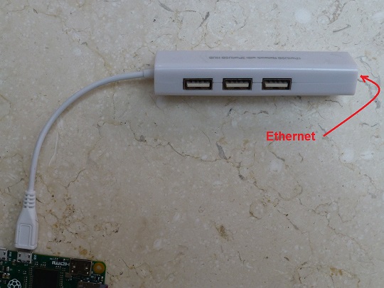
e.g. https://thepihut.com/products/ethernet-hub-and-usb-hub-w-micro-usb-otg-connector
Hardware Setup
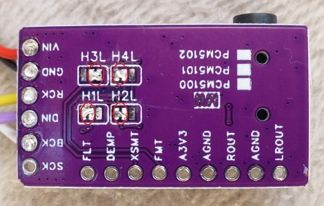
The PCM5102A module needs 4 solder bridges in the underside and one on the top. Sometimes the bottom ones are pre-soldered.
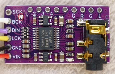
The I2S pins are defined by a dtoverlay setting later. 5 leads are required from the board - 2 power and 3 data/clocks.
| Board | Connect to | Pi | Function |
| SCK | NC | internal via link | |
| BCK | GPIO18 | pin 12 | data bit clock |
| DIN | GPIO21 | pin 40 | data |
| LCK | GPIO19 | pin 35 | data word clock |
| GND | GND | pin 6 or 14 | Ground |
| VCC | 5v | pin 2 or 4 | Power |
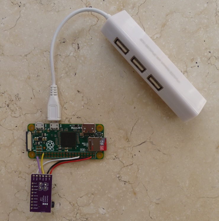
Connected up ready for power, ethernet and audio out.
Software setup
Raspberry Pi imager is the best option to setup the SD card. This does three important things in addition to loading the operating system. First it sets username and password. The earlier default 'pi' and 'raspberry' have been dropped as an obvious security risk. These details are encrypted so it is much easier to set via the imager that sorts this. It also can set WiFi details, and lastly will enable SSH so this does not have to be done separately. Download from: https://www.raspberrypi.com/software/
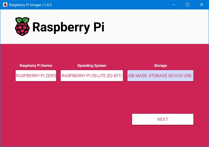
Open Imager and enter the Pi model, the firmware and the SD card.
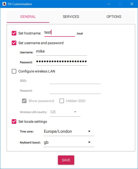
Then click ‘NEXT’ and select ‘EDIT SETTINGS’ to get the OS Customisation page. Enter hostname, username and password, WiFi details if required, and locale settings.
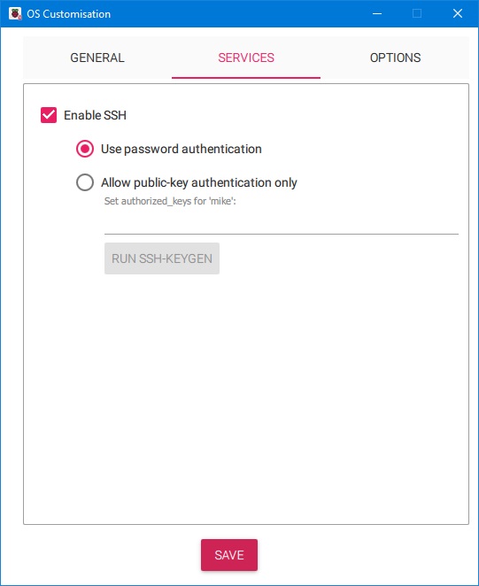
Next click the ‘SERVICES’ tab and Enable SSH and Use password authentication. The click ‘SAVE’ and then ‘YES’ to apply OS customisation settings. Then click ‘YES’ to continue to the Warning page.
The write will then start and progress bar will appear. The write will then be verified and confirmed OK and the card will be ready to remove.
Next connect the Pi to an Ethernet USB hub or Wifi dongle and to an amplifier, and plug in the SD card.
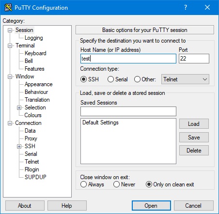
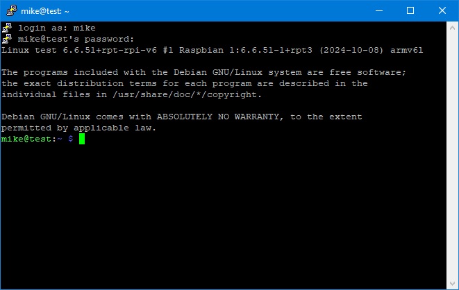
Now power up and wait a minute or so to load. Then start Putty on your PC (free from https://www.putty.org/). To connect enter the host name (entered as part of the sd card setup or the IP address (find by logging into your router). Port should be 22 and SSH selected.
Then log in and all is ready for updating and adding firmware.
The following instructions can be pasted into Putty. Copy text and right click in Putty to paste. This saves a load of time.
First update and upgrade:
sudo apt-get -y update
when complete:
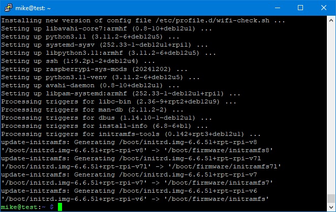
sudo apt-get -y upgrade
The latter takes a while (10-20mins) and sometimes fails due to not getting a connection. If it fails just enter the instruction again. All done:
We now need to edit some files to sort where the audio will go. First disable the (unsatisfactory) on-board sound:
sudo nano /etc/modprobe.d/alsa-blacklist.conf
This opens a text editor (nano). The file will be blank. Add:
blacklist snd_bcm2835
Then enter ^X followed by shift+Y, enter to save.
Next set the Pi to use the DAC:
sudo nano /boot/firmware/config.txt
comment out dtparam=audio=on (# in col 0)
and add:
dtoverlay=hifiberry-dac
at the end of the file.
^X, Y, enter to save.
Next add some alsa (sound) configuration:
sudo nano /etc/asound.conf
Paste the text below:
pcm.!default {
	type hw
	card 0
}

ctl.!default {
	type hw
	card 0
}
Save and exit (^X, Y, enter).
Now reboot. So:
sudo reboot
Leave putty open. When the Pi has restarted right click the task bar and select Restart Session. Log on again.
Now we can see if the DAC is connected:
aplay -l
Should give:
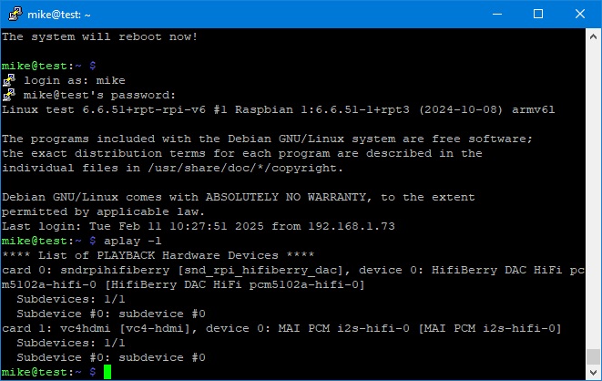
Now we can test the sound using:
speaker-test -D default -c 2 -twav
The speakers should be saying Front Left, Front right alternately. Stop with ^C.
Installing MPD and music files
The last two stages are installing the MPD music player (Music Player Daemon) and setting up the music and playlist files.
MPD is controlled by a program called MPC so both have to be installed:
sudo apt-get -y install mpd mpc
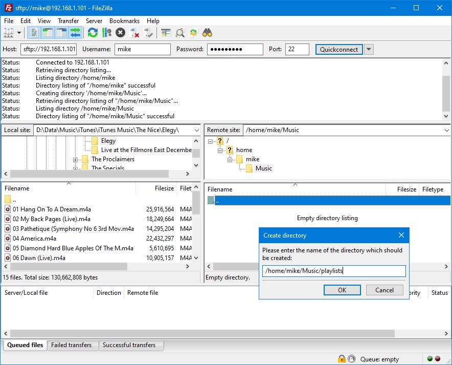
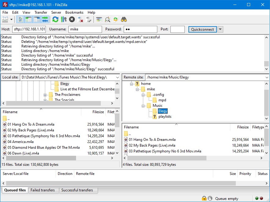
Next we need to add Music and playlists directories. This is done most easily using an ftp program that is also to easiest way to transfer music files. FileZilla is another great free open source program that will do this. Download from href=https://filezilla-project.org/download.php?platform=win64
Start FileZilla and enter the Pi IP address, username, password and 22 for the port and click Quickconnect. The Pi directory is on the right hand side. Right click in the lower box and select Create directory, then Music. Then click on Music to enter it and right click again to add a playlists directory.
Then add a .config directory and mpd directory within it. This is for additional files mpd requires. While we are here we might as well add some music. So add a directory in the Music folder with the album name (in my case Elegy). Open the new folder and drag and drop the music files from your PC.
The file structure should look something like: (FZ3)
Now we have to configure MPD. This needs more editing than under Buster.
sudo nano /etc/mpd.conf
Change the music and playlist directories as below. ~ is a shortcut for the users directory.
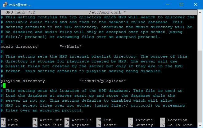
Next change the user to the Pi’s username (mike in this case).
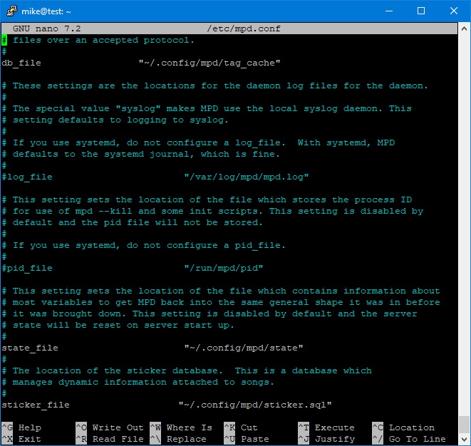
Now move the location of the other required files into .config/mpd/
Lastly go to the Audio output section and uncomment the alsa section (excepting the optional) and note the }:
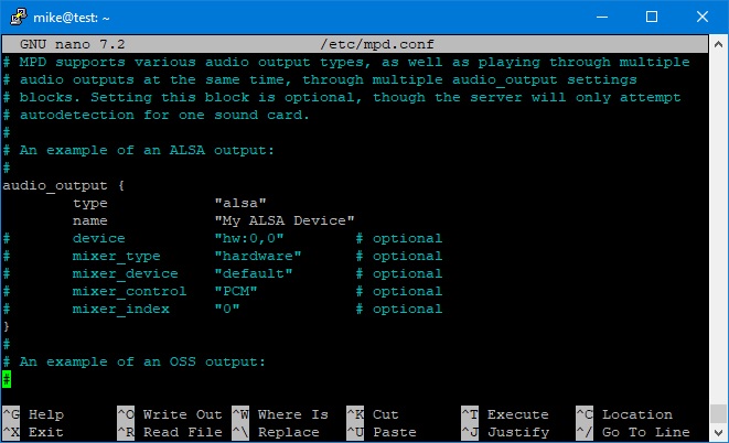
^X, Y, enter to save.
Last bit. Reboot to read new settings.
sudo reboot
Log on again. Get MPC to read the music files
mpc update
Now clear the list held ready to make a playlist
mpc clear mpc ls Elegy | mpc add
Save the playlist for the album.
mpc save Elegy
now clear with
mpc clear
and load the playlist with
mpc load Elegy
and play with
mpc play
At this point we have a music system working from the command line. Node-RED is a great option for a smartphone user interface. There is an MPD plugin that allows the two to communicate.
Adding software volume control (optional)
This is an optional step that adds a software volume control into the sound processing sequence. The key ingredient, that took a frustrating day to find, is that MPD needs the soft volume control to be called PCM.
sudo nano /etc/asound.conf
add the following:
pcm.sftvol {
    type            softvol
    slave.pcm       "plughw:0"
    control {
        name        "PCM"
        card        0
    }
}
Enter or change the pcm.!default section to:
pcm.!default {
    type             plug
    slave.pcm       "sftvol"
}
Save and exit (^X, Y, enter).
Now we can test it, as before:
speaker-test -D default -c 2 -twav
This should give alternating "front right" and "front left" from the respective speakers.
For an example of this being used with a music/radio player see: