Arduino Smartphone Coms/Serial Monitor Via Bluetooth HC-05, HC-06
This is incredibly useful if you want to test your sketch in a real world environment, away from your PC. The outcome is that your smartphone acts the same as the Arduino serial monitor on your PC. The HC-05 and HC-06 Bluetooth modules are available for around £3 on ebay and there are many free smartphone apps to choose from. There are a few pitfalls that you will hopefully avoid by following the examples here. The free smartphone app used here can also save the text received to a file for later use. There is no change required to your sketches as the same serial pins are used.
I first used this when testing a device that measures the distance cars give when overtaking me on my bicycle. I was able to record distance measurements taken 30 times a second onto my phone where they were saved into a file. I analysed this later with video that I also recorded using a sports cam and my tracking app that gave my speed and location.
You will need:
- Your favourite Arduino (Uno used here)
- HC-05 or HC-06 Bluetooth module
- A smartphone (Android phone used here) and free Bluetooth app
Steps:
- Install free Bluetooth app
- Configure Bluetooth module
- Connect Bluetooth to Arduino
- Load example sketch
- Test system
Install Bluetooth App

There are many Bluetooth apps available and many are free. I use Android phones but I expect the same is the case for the other systems. I decided to use BlueTerm 2 as it also provides the option to log the data received to file. I also found it very straightforward to use. So go to Google Play and request download of BlueTerm 2.
When you have the app installed you can connect to Bluetooth devices. Note that Bluetooth devices first need to be paired with the phone before they can be used in any apps:
Turn on BlueTooth: I go via Settings>Bluetooth.
The phone will list already paired devices and after a few seconds then show Available devices. The name might initially show as a set of numbers rather than the device name. However selecting it then shows the name and asks for the PIN that is usually 1234.
Now start BlueTerm 2. Click settings, then click Connect device and select as required. You can just power up a HC-05/HC-06 module at this stage and check the pairing process if you wish (attach negative supply to ground and 5v to Vcc).
Configure Bluetooth Module - Part 1 - Connections and HC-06
If you hare happy to use the default name and baud rate you can skip this step. The defaults are name: HC-05 or HC-06 and baud: 9600. The benefit of re-configuring the module is that faster baud rates can be selected and the name can be set to something more easily recognised.
Configuration needs commands to be sent from a PC to the module via a serial connection. A FDTI USB serial link is ideal, especially if it has a 3.3v option. However Arduino boards have a USB to serial converter and hence this can also be used and this is the method shown here. In order to do this it is best to disable the Arduino main processor serial port so we can communicate between PC and the Bluetooth module without interference.
The sketch to disable the Arduino serial simply has the instructions:
pinMode(0,INPUT):
pinMode(1,INPUT);
in the setup{} section.
You can download the sketch NoSerial.ino. Create a folder called ‘NoSerial’ in your sketches folder and add NoSerial.ino to this. Start the Arduino IDE, navigate to File>Sketchbook>sketches>NoSerial to open the sketch. Select the board type and Port from the Tools menu and click the download button.
Connection for configuration
With sketch loaded we can now connect the Bluetooth module to the Arduino board. The Tx and Rx connections are swapped compared to what we will do later as we want to communicate with the PC port for the Serial Monitor and not the Arduino main processor. The PC Tx is connected to the Arduino Rx and vice versa.
Note that the Bluetooth modules have 3.3v levels for Tx and Rx. Hence a voltage divider should be used for the Bluetooth Rx input when connecting to 5v systems. The Bluetooth 3.3v Tx output is usually detected fine by 5v systems and hence can be connected directly.
I have found that a voltage divider using 3k3 and 6k8 resistors works up to 115200 serial baud rates.
The HC05 and HC06 modules have on-board voltage regulators and hence run with Vcc connected to 5v.
So connect :
- 3k3 resistor to D0
- 6k8 resistor to ground
- Connect the other ends of the two resistors together, and to the Rx pin on the Bluetooth module
- Connect the Bluetooth module Tx pin to D1
- Connect the Bluetooth module ground pin to GND Connect the Bluetooth module ground pin to GND
- Connect the Bluetooth module Vcc pin to 5v
See picture for detail.

In order to configure the module it needs to be set into AT mode. The procedure is different for the HC-05 and HC-06 modules.
HC-06
These are the easiest. They set themselves into AT mode if they are not paired with any device. However the baud setting will be whatever the normal operating baud has been set to. This is normally 9600 when supplied. If this does not work try 38400 or the other common rates.
Connect the USB lead from PC to Arduino and start the Arduino IDE. The Bluetooth LED will flash rapidly (~4Hz) when in AT mode.
Open the Arduino Serial monitor via Tools>Serial Monitor. Set the baud to 9600 and set ‘No line ending’.
Now enter AT and click Send. If all is working you will see ‘OK’ returned to the monitor. If nothing comes back double check the wiring and try different Baud settings.
With an OK confirming good communications we can change the name and set out own Baud rate.
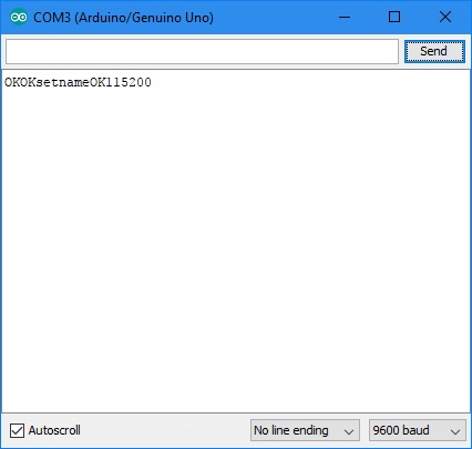
Enter AT+NAMEARDUINO and click send. This sets the module name to ARDUINO. Any other text can be used. Note no spaces in the command.
The reply should be OKsetname. This gets added to the OK sent earlier
Now enter AT+BAUD8. This sets the baud to 115200.
The reply should be OK115200. If any more AT commands are to be sent the Serial Monitor baud setting must be changed to 115200.
Other rates can be set. Baud4 is 9600, Baud5 is 19200, Baud6 38400, Baud7 57600. There are higher settings than 115200 but check first that your PC and Arduino can accept them (mine cannot exceed 128000). Note - If you set a rate that is too high you will not be able to communicate with it to set it back!!!
Configure Bluetooth Module - Part 2 - HC-05 and Initial Test
HC-05
These have the complication of having to be manually set into AT mode. The manual says that if AT mode is triggered after power up the Baud setting will continue at the rate already set for normal communications. I could not get this to work! If however AT mode is set at power on the baud is set to 38400. Hence this latter option is the most reliable as we can be sure the baud is 38400.
Open the Arduino Serial monitor via Tools>Serial Monitor. Set the baud to 38400 and set ‘Carriage Return’.
The next step is the get the board into AT mode. This is where most problems arise because of differences in the carrier boards.
The fundamental process is to hold the ‘Key’ pin (pin 34) low a few seconds on power-up.
My board has a button to do this (the two additional connection pins are EN and STATE). Disconnect the Vcc wire from the Bluetooth module. Then, while holding the button pressed, reapply 5v to Vcc. The LED should flash at approximately 2 second intervals. I hold the button until the second flash.
Some boards have a Key pin as one of the 6 pins to the module. If so tie this to 3.3v during powering up.
Some boards have neither and users have had to solder a button between the Key pin (34) and 3.3v (pin 12). See manual hc-05_06-datasheet.pdf.
With the LED slowly flashing we can check the communications. Enter AT and click Send. The response should be OK. I found that this reply was continually repeated until I sent a blank line – just click send. If you get ERROR:(0) then send a blank line and then send AT.
Now set a new name. Enter AT+NAME=ARDUINO The reply should be OK. However in my case the module reset out of AT mode (LED flashing quickly). I could not find the cause and this also happened when using a FDTI serial connection rather than the Arduino. I got back into AT mode as before: Disconnecting the power wire to the board and reconnecting while the button was pressed. Later checks showed that the name had been changed.
Next set the Baud. Enter AT+UART=115200,1,0 The reply should be OK. However it did sometimes jump out of AT mode as above.
The UART setting can be checked with the command: AT+UART? The reply should be OK and +UART=115200,1,0
Initial test

At this stage we have the PC with a serial connection to the Bluetooth module. So an initial, optional test can be done by starting the smartphone BlueTerm 2 app (assuming the module has already be paired with the phone). Connect to ARDUINO. Set the Arduino Serial Monitor to 115200 baud. Type 'Hello World' and click send. This should now appear on BlueTerm 2. Now type 'Hello to you' into BlueTerm 2. This should now appear in the Serial Monitor.

Connect Bluetooth Module to Arduino
We need to load our Arduino test sketch first. Download BTtest.ino. This sends a number every 0.5s and then increments it, rolling over to 0 from 255. Create a folder called BTtest in your sketches folder and add BTtest.ino
The Arduino serial connection is also used for downloading sketches. So the two wires to the Bluetooth module must be disconnected so that it does not interfere.
After downloading the sketch reconnect the Bluetooth module. Note however that the Tx and Rx on the Arduino need to be swapped compared to the earlier configuration setup.
So connect :
- 3k3 resistor to D1
- 6k8 resistor to ground
- Connect the other ends of the two resistors together, and to the Rx pin on the Bluetooth module
- Connect the Bluetooth module Tx pin to D0
- Connect the Bluetooth module ground pin to GND Connect the Bluetooth module ground pin to GND
- Connect the Bluetooth module Vcc pin to 5v
See picture for detail.


Now power up the Arduino. It does not need to be connected to a PC.
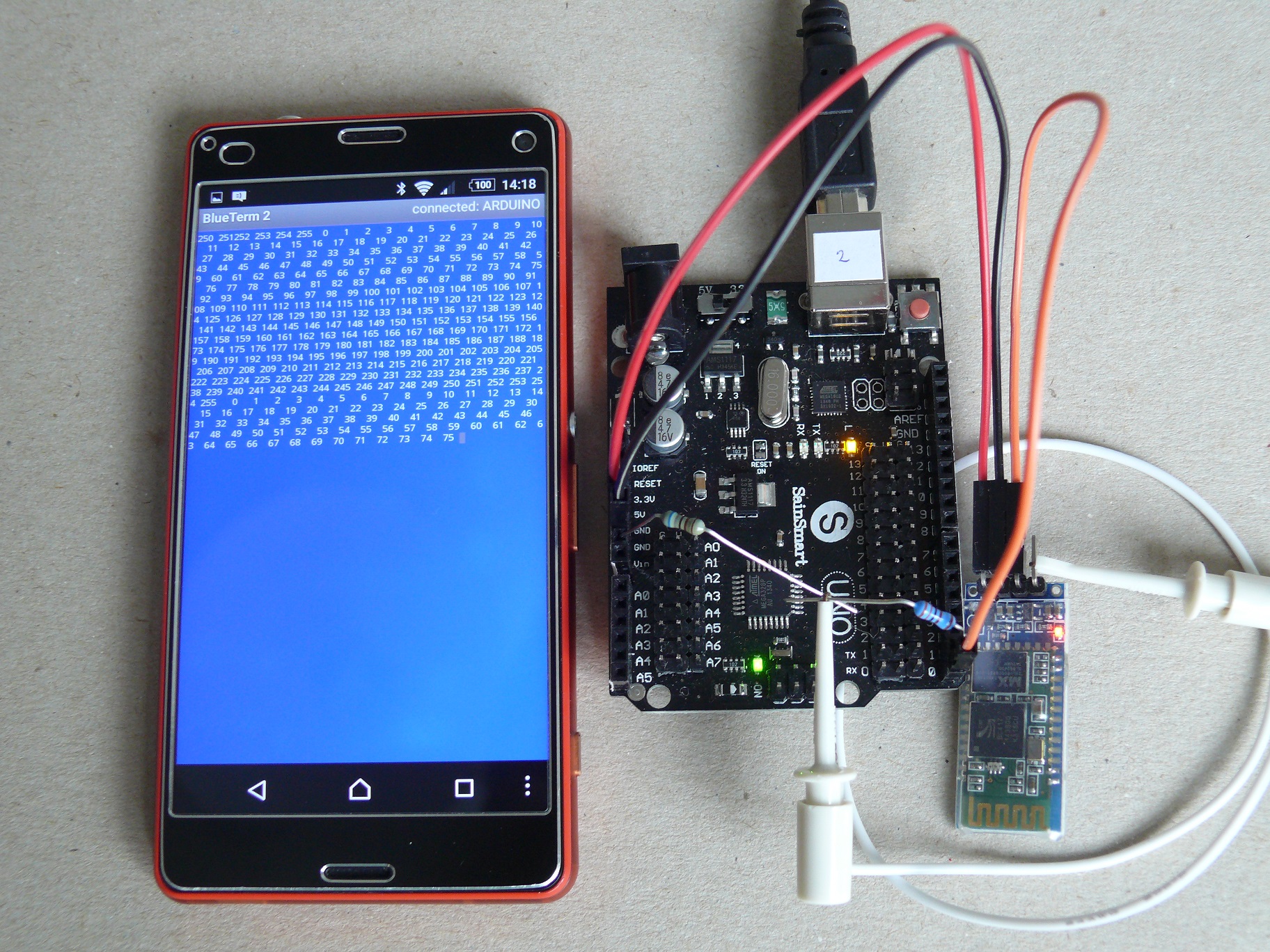
Pair the board to the smartphone if not already connected (see Install Bluetooth app above). Then start BlueTerm 2, click settings, then click Connect device and select ARDUINO. You should see the screen fill with numbers incrementing from 0 to 255.
I hope you find this as useful as I have.Mike