SIMPLE, LOW COST AND ACCURATE STEPPER MOTOR DRIVER

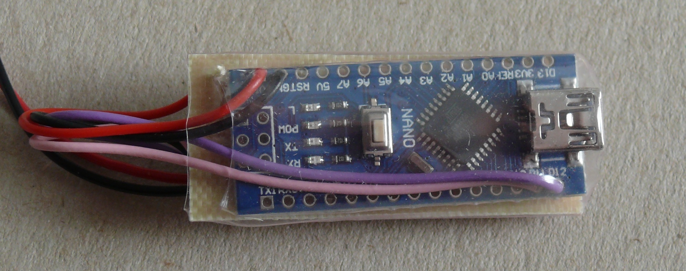
I built this to drive the stepper motor on a telescope mount. The requirement was for an accurate 12rpm that would make the telescope mount rotate to counter the earth’s rotation. The mount had a motor and gears installed but the commercial electronic ‘tracker’ was hugely more expensive than the system here. I tried to write the code in a way that could be easily modified for other speeds, and could be used as a starting point for more complicated systems. The ‘rpm = 12;’ line is right at the start so in many cases you will just need to change this number. It should work on most Ardunio boards. I started on a Uno and then went for a Nano for the final unit. It is set up for an Arduino with crystal frequency of 16Mhz and hence will need the timer pre-scaler code adjusting for other frequencies.
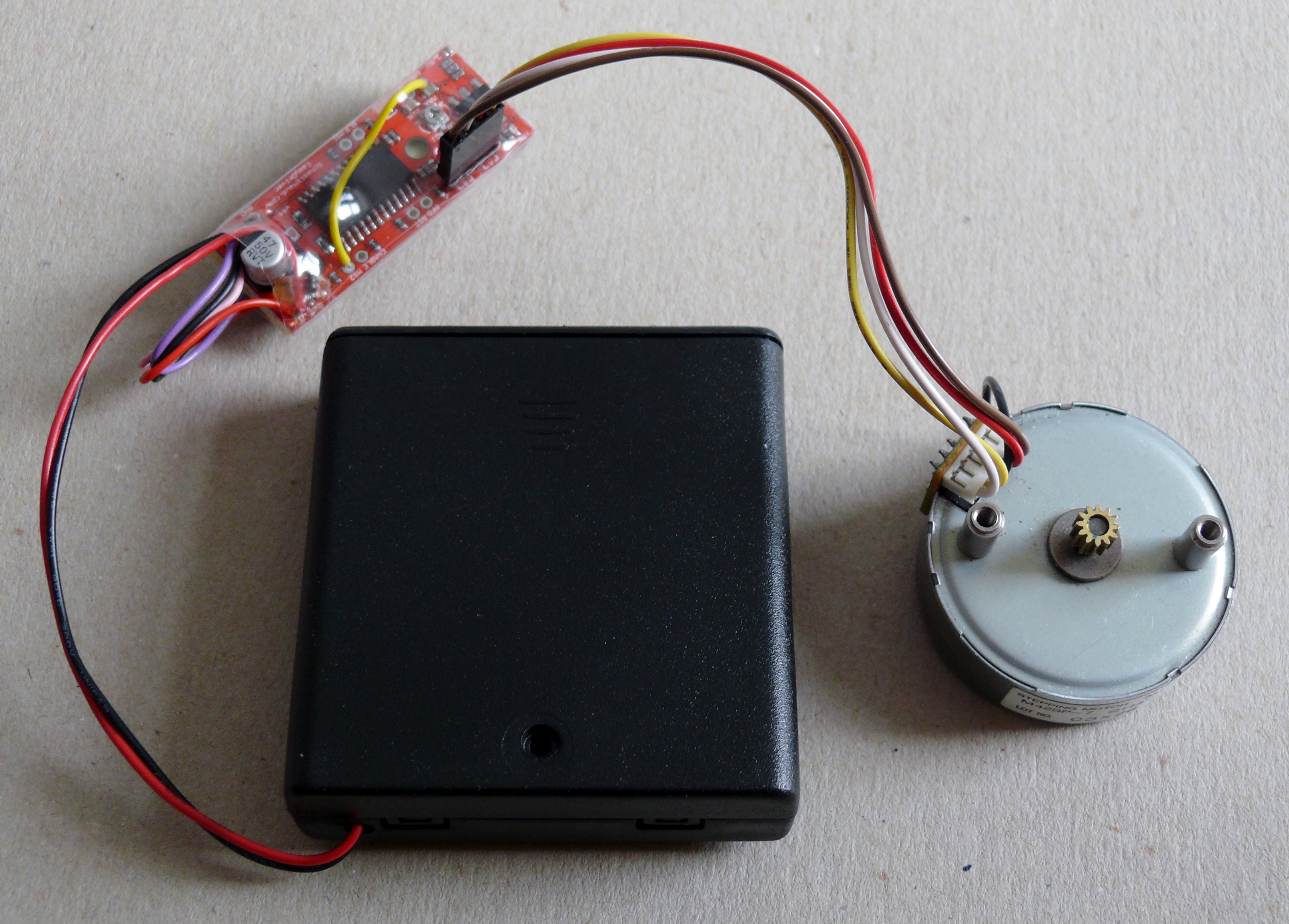
You will need:
- Arduino, e.g. Uno or Nano
- EasyDriver board
- Power supply – 4 AA batteries used here
- Stepper motor
The EasyDriver board takes a lot of hard work out of the Ardunio. It just needs two inputs – direction and step. It can be setup for single, half or ¼ or 1/8 microstepping with the latter being the default. It can drive up to 700ma per phase, up to 30v. I wanted the extra torque of the half step mode and hence set it up for this. Although designed for two bipolar windings it can also drive unipolar motors by ignoring the middle tap in each winding. In some cases the middle taps of the two windings are connected (as was the case here). If so this connection has to be removed. In this case it just required a cut in a track on the motor connection PCB.
Connections

Connections:
· On EasyDriver board – EN2 to GND (next to +5V) (to set half stepping)
· Positive supply to EasyDriver M+ PWR IN and wire from here to Vin on the Nano
· Negative supply to EasyDriver GND PWR IN
· Three wires from EasyDriver GND, STEP, DIR to the Arduino GND, D12 and D11 respectively.
Check using the wire colours and photos above.
I found that 6v was enough for the stepper motor. If you need to go higher check the voltage regulator chips on both boards to make sure they don’t get too hot.
Firmware (sketch)
Download: Stepper.ino
The normal ‘void Loop()’ function does not work well when trying to get precise timings. One can add and tune ‘delay();’ statements but this gets very complicated once one adds additional functionality that does not run every time – e.g. code associated with a button being pressed. A better way is to use one of the internal timers to trigger an interrupt routine. A very good explanation on how to do this is at: https://www.instructables.com/id/Arduino-Timer-Interrupts/ . A very nice feature of the ATMEL microcontrollers is a the ability to set a trigger value for a timer that both runs the associated interrupt code and resets the timer to zero for the next interrupt. Ideally the interrupt function should have minimum code. The code here takes some beating. It also does all the work necessary for this application so no code is needed in the ‘void Loop()’ function. However code is likely to be needed in ‘void Loop()’ if additional options were needed such as changing the speed or sending information to a display.
The interrupt routine just uses an ‘exclusive or’ statement to toggle the step output. Hence a nice, equal mark– space square wave is produced, using two interrupts to give a high and low to input one ‘step’ to the EasyDriver board. The use of the PORTB and PINB functions gives much smaller machine code than the alternative of digitalRead(); , if statement and digitalWrite();
The direction is set in 'void Setup()'.
The code as written goes down to 1rpm. It can go less if ‘rpm’ is made a ‘float’ or the code adjusted so integer rpm number represents say 0.1 rpm increments. The number that ends up in the ‘settmr1()’ call must be less than 65535 as the timer is 16 bit. This may need the timer pre-scaler adjusting. For the best accuracy the pre-scaler should be set so that the ‘settmr1()’ number is a close as possible to 65535 without ever being greater.
For those who might be interested the detail of the timer calculation is as below.
First find how frequently the interrupt routine has to operate.
Motor is 48 steps/rev with the driver doing half stepping. So there are 96 steps per rev. We also need two interrupt calls per step (one to high and one back to low) so we need 96*2 interrupt calls/rev.
For x rpm we have 1/x mins/rev, or 60/x seconds/rev.
The interrupt timing must then be 60/ (x*96*2) seconds
Second we need to find what timer count gives the required interrupt timing.
The system clock is 16Mhz or every 1/16000000 seconds.
The timer prescaler is 256 so the clock is incremented every 256/16000000s or every 16 us.
So for the timer to give the required interrupt timing it must count to 60*1000000/(x*96*2*16).
This factors down to the formula in the sketch = 312500/(x*16).
For 12 rpm the count is 1628 (rounded).
For 1 rpm the timer count needs to be 19531 (rounded).
Both of these numbers are lower than the max count of 65535 and hence this prescale is suitable for rpms >1. A lower prescaler of 8 could be used for increased accuracy at 12 rpm. The prescale value can only be 1, 8, 64, 256, 1024.
I hope this gets you started with accurate stepper motor operation. Please ask if you feel I have missed anything.